Automobile components often experience random excitations from road inputs and periodic vibration from engine firing. Replicating these factors in a lab, on a shaker bench, can significantly help manufacturers design and validate products to meet durability requirements.
Vibration Testing Methodologies
Random Vibration Test
Typically used to simulate road excitations and testing of Body/Frame mounted components. For components mounted on engine and transmission, Random Vibration is coupled with periodic excitations.
The test specimen is tested with the time series data collected either on representative road surface or surfaces representing the full durability schedule.
Random Vibration consists of all excitation frequencies, which is independent of resonance frequency of the test product.
Often, simulated signals will always be lesser than the actual road input, hence kurtosis setting is applied in order to match both.
Frequency Sweep Test
Typically used for known frequency range and for quick failure replication.
A test will be conducted by sweeping back and forth around the resonance frequency and the vibration amplitude the component could be experiencing in the failure environment.
Variants: Fixed Frequency Test, Frequency Tracking & Dwell Test.
Sweep Sine on Random Test
Typically used to simulate all vibrations. Sine portion covers dominant engine firing orders, and random portion covers all vibration including road excitations. Used for engine and power train mounted components.
During the test, the shaker will generate the random vibration per the requested PSD with all frequency content existing simultaneously. At the same time, sinusoidal signals will be generated, and frequencies will be sweeping up and down.
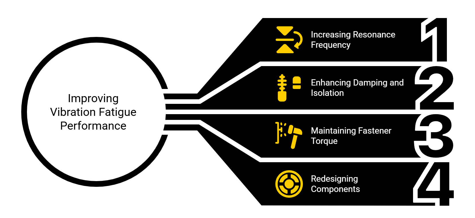
Steps to improve the performance against Vibration Fatigue
- Increasing the resonance frequency of the structure by reducing the weight, if possible, or by increasing the stiffness of the structure. Stiffness of the structure can be improved by adding features such as ribbing, gussets, bosses, flanges, beads, darts, and adding attachments.
- Increasing damping and isolation in order to reduce amplification factor. Examples: adding rubber grommet on engine mounted component, adding rubber isolation on oil indicator tube.
- Maintain torque of fasteners during service to sustain the stiffness of the structure for components which are joined to a vehicle by fasteners.
- Lastly, redesigning the component. Ideally, engine mounted components should be designed to have the first resonance frequency above the engine operating range and cantilever design should be avoided in designing body/frame mounted components.
It is always recommended that vibration analysis of the component be done in the earlier design process phase or before tooling, in order to avoid delays during qualification and launch.
This article is based on research paper